
Special electronic circuits – drivers – allow you to extend the life of the LEDs, make their glow uniform and of high quality. We will learn how this device works, how to choose and install it correctly, and how to make it yourself.
- What is a driver and why is it needed?
- The principle of operation, the classic circuit and the difference from the power supply
- Specifications
- Types of drivers
- Linear and impulse
- Electronic, dimmable and capacitor based
- With and without body
- Best before date
- How to choose a driver for an LED lamp?
- How to check if it works?
- Connection
- How to make a driver for an LED lamp with your own hands?
What is a driver and why is it needed?
LEDs are very sensitive to changes in the parameters of the mains, so they are connected to the network through a driver – an electronic device that controls the current and voltage. Typically, a driver for a led lamp is selected with a margin of power and taking into account the range of output voltage and current. If its parameters do not fit the LED device, it will become unusable, it will have to be disposed of.
The principle of operation, the classic circuit and the difference from the power supply
Even though a driver is often referred to as a power supply, there is a difference between the two. The driver is a source of current that maintains its constant value for passing through the LED, and the power supply maintains a stable voltage. Consider how the power supply works on a specific example:
- Connect a resistance (R) of 40 ohms to a 12 V source.
- Let a current (I) of 300 mA flow through the resistor. With two resistors installed, the current will double to 600 mA. In this case, the voltage will not change, since it has a proportional relationship with current and resistance (Ohm’s law I \u003d U / R).
Now let’s see how the driver works:
- Let a 30 Ω resistor (R) be included in the circuit with a 225 mA driver.
- If, at a voltage (U) of 12 V, two 30 Ohm resistors connected in parallel are connected, the current will remain the same – 225 mA, and the voltage will become half as much – 6 V.
The driver eventually provides the load with a given output current, regardless of power surges. Therefore, the LEDs, which will be supplied with a voltage of 6 V, will shine as brightly as with a source of 10 V, if a given level of current is applied to it. LED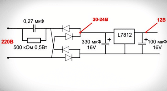
- capacitance for voltage separation;
- rectifying module;
- stabilizer.
How the circuit works:
- When a current is passed, the capacitor C is charged until it is fully charged. The smaller its capacity, the faster it will charge.
- Alternating current is converted to pulsating. The first part of the wave is smoothed out as it passes through capacitor C.
- The electrolytic capacitor that completes the circuit serves as a smoothing filter-stabilizer.
Specifications
When buying an LED lamp, you may need to purchase a driver if the lighting device does not have a current converter. Main characteristics:
- output current, A;
- operating power, W;
- output voltage, V.
The output voltage may vary. It depends on the power connection scheme and the number of LEDs. The level of brightness and power depends on the magnitude of the current. In order for the diodes to shine brightly and not dim, the current at the output of the driver is maintained at a given level. The power of the converter should be slightly higher than the total number of watts of all diodes. To calculate the power of the driver, the formula is used: P \u003d P (led) × X where:
- P (led) is the power of one LED;
- X is the number of diodes.
If the calculated power turned out to be 10 W, the driver must be taken with a margin of 20-30%.
Types of drivers
All drivers are distinguished according to three criteria – according to the method of stabilization, design features and the presence / absence of protection. Let’s consider all the options in more detail.
Linear and impulse
Depending on the current stabilization circuit, drivers are divided into two types – linear and pulse. They differ in principle of operation and efficiency. Before the electronic circuit of the driver, the task was set – to ensure stable values of current and voltage supplied to the crystal (LED). The simplest and cheapest option is to include a limiting resistor in the circuit. Linear power scheme: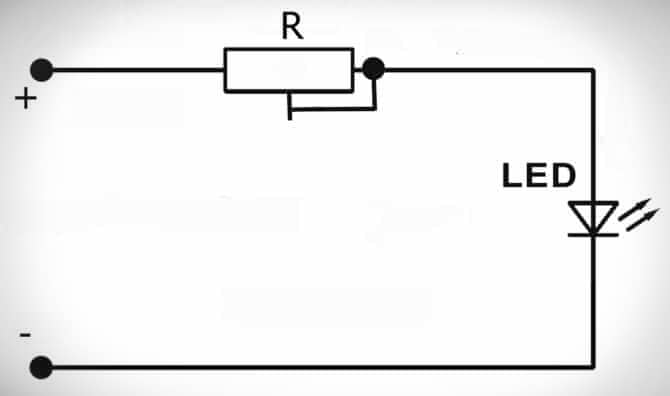
- simplicity;
- cheapness;
- relative reliability.
Along with linear circuits, current and voltage can be stabilized by pulse stabilization:
- after pressing the button, the capacitor is charged;
- after releasing, the capacitor discharges, giving the stored energy to the semiconductor element (LED), which begins to emit light;
- if the voltage rises, then the charging time of the capacitor is reduced, if it falls, it increases.
The user does not have to press the button – the electronics do everything for him. The role of the button mechanism in modern power supplies is performed by semiconductors – thyristors or transistors. The considered principle of operation is called pulse-width modulation in electronics. Dozens and even thousands of operations can occur per second. The efficiency of such a scheme reaches 95%. Simplified scheme of impulse stabilization: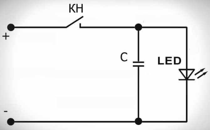
Electronic, dimmable and capacitor based
The scope of its application and performance characteristics depend on the principle of the driver device. Types of drivers according to the principle of the device:
- Electronic. Their circuits necessarily use a transistor. A capacitor is installed at the output, eliminating or at least smoothing out current ripples. Electronic converters are capable of stabilizing currents up to 750 mA. Electronic type drivers struggle not only with ripples, but also with high-frequency electromagnetic interference induced by electrical appliances (radio, TV, router, etc.). Minimize interference allows the presence of a special ceramic capacitor. The minus of the electronic driver is the high cost, plus the efficiency is close to 95%. They are used in powerful led-lamps: car headlights, spotlights, street lamps.
- Dimmable. A feature of dimmable drivers is the ability to control the brightness of the lamp. The adjustment is based on a change in the output current, which determines the brightness of the light flux. The driver can be included in the circuit in two ways: between the lamp and the stabilizer or between the power source and the converter.
- Capacitor based. These are inexpensive models used for low cost LED fixtures. If the manufacturer did not provide a smoothing capacitor in the circuit, then a ripple is observed at the output. Another disadvantage is the lack of security. The advantage of such models is high efficiency, tending to 100%, and simplicity of the circuit. Such drivers are easy to assemble with your own hands.

Capacitor drivers can cause flicker and are therefore not recommended for use with indoor appliances. Flicker adversely affects vision and irritates the nervous system.
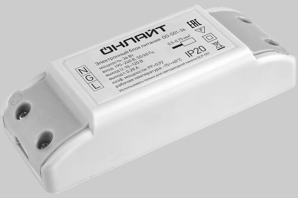
With and without body
The driver may or may not be placed inside a protective case. Electronic circuits are vulnerable to many external factors, so placing the driver in a case is considered a more reliable option. The housing protects the electronic converter from moisture, dust, direct sunlight, etc. Unpackaged models are cheaper, but they have a shorter service life and worse operational stability. They are more suitable for flush mounting.
Best before date
The driver is rated for approximately 30,000 hours. This is slightly less than the estimated life of many LED fixtures. Such a decrease is associated with unfavorable factors in which the current stabilizer has to work. What negatively affects the operation of the driver:
- power surges;
- temperature and/or humidity changes.
If a 200 W appliance is loaded with 100 W, then 50% of the nominal value is returned to the network. This can cause overload and power failure.
The life of the driver is limited by the life of the smoothing capacitor. Over time, the electrolyte evaporates in it, and the device fails.
To prolong the operation of the driver, it must be operated in rooms with normal (not high) humidity, and connected to a network with high-quality voltage without surges.
How to choose a driver for an LED lamp?
When connected to a current stabilizer, semiconductors receive the power they need and reach their nominal characteristics. The service life of the diodes depends on how correctly the driver is selected. What parameters to pay attention to:
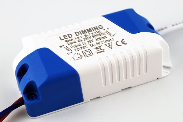
- Power. It determines the maximum allowable load for which the device is designed. For example, marking (20×26)x1W means that from 20 to 26 LEDs can be connected to the driver simultaneously, each with a power of 1 W.
- Current and voltage (nominal values). Manufacturers indicate this parameter on each LED, it is for it that a driver is selected. If the maximum rated current is 350mA, a 300-330mA power supply must be connected. Such a range of operating currents allows you to ensure the shelf life of the lamp, provided by the manufacturer.
- Protection class. It depends on this indicator where exactly the lamps can be used – outdoors or indoors. The class of moisture resistance and tightness is indicated by the letters IP and is expressed in two numbers. The first digit is used to judge the protection against solid fractions (dust, dirt, sand, ice), the second – from liquid media. The protection class does not indicate the temperature at which the luminaire can be used.
- Frame. The driver can have an open perforated metal case or a closed one. In the second case, the device is placed in a metal box. For home use, an unsealed plastic case is suitable.
- Principle of operation. The limiting resistor does not eliminate voltage fluctuations in the mains and does not protect against impulse noise. The slightest change in voltage leads to sudden surges in current. Linear regulators are considered unreliable and low efficiency drivers, switching circuits are preferred.

How to check if it works?
To check the driver without load, it is enough to apply 220 V to the input of the block. If the device is working properly, a constant voltage will appear at the output. Its value will be slightly greater than the upper limit indicated on the driver label. If, for example, the stabilizer has a range of 27-37 V, then the output should be about 40 V. To maintain the current in a given range, as the load resistance increases (it tends to infinity without load), the voltage also grows to a certain limit. This verification method is simple and accessible, but does not allow to draw unambiguous conclusions about the 100% serviceability of the device. There are drivers that, after being turned on without load, do not start or behave in an incomprehensible way. Second check option:
- Connect a resistor to the output of the driver, choosing its resistance based on Ohm’s law. For example, the driver power is 20 W, the output current is 600 mA, the voltage is 25-35 V. The desired resistance will be 38-58 ohms.
- Select a resistance from the specified range and with the appropriate power. Even if it is small, then this is quite enough for verification.
- Connect a resistor and measure the output voltage with a tester. If it is within the specified limits, then the driver is definitely working.
When searching for breakdowns, it is necessary to take into account the principle of the circuit design. In linear and pulse circuits, breakdowns can be associated with certain problems. Possible malfunctions:
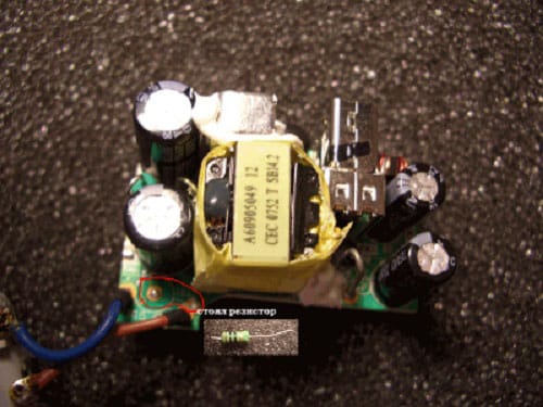
- In linear stabilizers , a pair of resistors with a resistance of 5 to 100 ohms is used to protect against voltage drops. One is at the input of the diode bridge, the second is at the output. To reduce flicker, a capacitor-electrolyte of maximum capacity is switched on in parallel with the load. Linear driver failures can be associated with the burnout of one or two protective resistors at once.
- In pulse current converters, microcircuits are protected from overload, overheating and overvoltage and, in theory, cannot break. In fact, any microcircuit, especially in Chinese-made drivers, can become unusable. The problem is compounded by the fact that many Chinese chips are hard to find replacements. Some of them cannot be found even on the Internet.
Connection
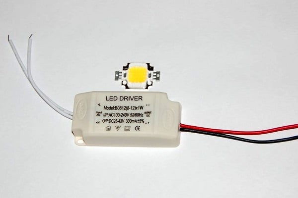
Connecting the driver to the LEDs does not cause difficulties for users, since there is the necessary marking on its body. How to connect the driver:
- Apply input voltage to the input wires (INPUT).
- Connect the LEDs to the output wires (OUTPUT).
When connecting, observe the polarity:
- Polar input (INPUT). If the driver is powered by constant voltage, then connect the “+” output to the same pole of the power source. If the voltage is AC, pay attention to the markings on the input wires. There are two options:
- “L” and “N”. Apply the phase to the output “L” (find it with an indicator screwdriver), to “N” – zero.
- “~”, “AC” or no marking – you can not observe the polarity.
- Polar output (OUTPUT). Observe polarity at all times. Connect the “+” wire to the anode of the 1st LED, “-” to the cathode of the last one. All semiconductors are connected in series – the anode of the next one is attached to the cathode of the previous one.
There is a second option for connecting LEDs – several chains containing an equal number of diodes are connected in parallel. When connected in series, all elements glow the same, with a parallel version, the lines may have different brightness.
How to make a driver for an LED lamp with your own hands?
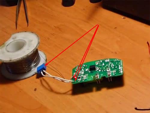
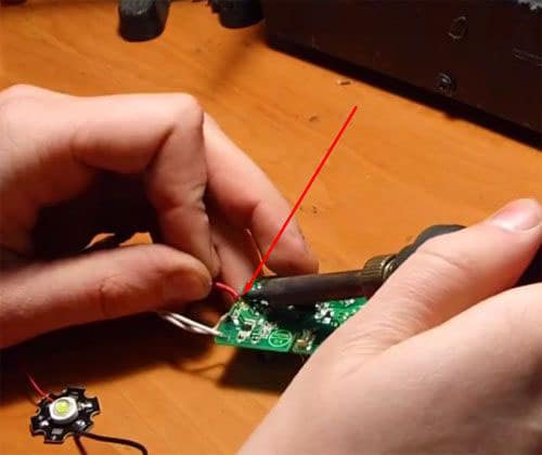
The driver can be made from an old phone charger. It is only necessary to make small changes to the chip. Such a homemade product is enough to power 3 LEDs with a power of 1 W each. Consider step by step the assembly of the driver from the phone charger:
- Remove the case from the charger.
- Using a soldering iron, remove the resistor that limits the voltage supplied to the phone.
- In place of the soldered resistor, put a tuning resistor. Set it to 5,000 ohms.
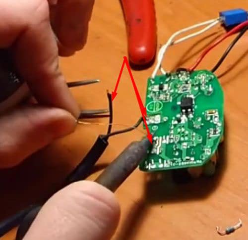
- Solder the LEDs in series to the output channel.
- Unsolder the input channels and solder a 220V power cord instead.
- Check the operation of the circuit by setting the voltage on the resistor with the regulator so that the diodes burn brightly, but do not change colors.
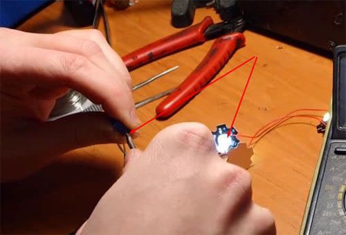


When performing work on creating a diver from a charger, you must adhere to safety regulations. If you touch the bare parts, you can get a strong electric shock.
The driver can also be built from scratch. To do this, you need a soldering iron, a tester, wires and an integrated stabilizer KR142EN12A (or a foreign analogue – LM317), which can be purchased at any specialized store for 20 rubles. The parameters of the purchased microcircuit are 40 V and 1.5 A current. It has built-in protection overload, overheating and short circuit. The microcircuit stabilizes the voltage, and the driver equalizes the current, so you will need to make changes to the standard circuit for connecting the microcircuit. Driver on an integrated stabilizer: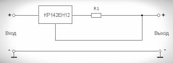
- R – resistance, Ohm;
- I – current, A.
Driver build order:
- Assemble a 9.9 V current regulator with a current of 300 mA. Then R1 \u003d 1.2 / 0.3 \u003d 4 ohms. Resistor power – from 4 watts. You can take the resistors that are used in TVs. They can also be bought in stores. The power of these elements is 2 W, the resistance is 1-2 ohms.
- Connect resistors in series. Their resistance will add up and will be equal to 2-4 ohms.
- Attach the chip to the heatsink and connect a circuit of series-connected diodes to the output of the driver. Observe polarity when connecting LEDs.
- Apply a constant voltage of 12-40 V to the input (the device is designed for 9.9 V, so we take it with a margin). It is not worth exceeding the limit value – the microcircuit may burn out. The supplied voltage may not be stabilized. You can use a car battery, a laptop power supply or a step-down transformer with a diode bridge. Connect the driver, observe the polarity – the job is done.
Thanks to the drivers, it is possible not only to improve the performance of LED lamps, but also to ensure their long, uninterrupted operation. Considering the cost of LED fixtures, the use of drivers becomes a cost-effective solution.


Статья интересная, понятно написано. Но по мне лучше купить готовый драйвер, чем разбираться в схемах. Хотя и здесь могут быть подводные камни – не на всех лампах пишут точные данные и по незнанию можно просто спалить светильник, купив драйвер не под нужную мощность или напряжение. Подбирал драйвер для светодиодной ленты в машину, которая была без маркировки, так и не смог выбрать. Пришлось просить сделать драйвер друга, который разбирается в электрике. Правда и ему пришлось повозиться, пока вычислил все характеристики.
Благодаря данной статье смог самостоятельно разобраться в работе и установке драйвера для светодиодных светильников. Установил у себя на кухне без всяких проблем и мастеров. По поводу указанных вами недостатков не согласен, если хорошо вчитаться то можно совершенно точно понять что и как работает. Плюс по характеристике можно было узнать в магазине. Буду и дальше читать статьи на этом сайте. Всем советую.
Я считаю с драйверов работа того же светильник будет на много надежнее,т.к если просто купить обычный светильник, он про служит не долго,и хорошо если еще и не будет замыкать.Лучше по читать схему драйвера и установить,за то раз и на долго.
Достаточно информативная статья, которая позволяет понять само назначение драйвера светодиодного светильника и навсегда закрыть вопрос о мерцании лампочек. Приспособление полезное, поскольку светодиодные лампочки практически вытеснили обычные лампы накаливания. Порадовало, что есть схема сборки собственного драйвера. Я хоть и купил готовый драйвер, но, ради эксперимента, решил проверить схемы сборки драйвера вручную. Оба драйвера работают одинаково. Схемы актуальные, поэтому есть смысл собрать его самостоятельно и не тратить лишних средств.
сколько воды.При подключении драйвера с напряжением 37в без нагрузки никогда на выходе не будет 40 в, будет напряжение заряженного конденсатора на выходе.
Как проверить работоспособность? Чтобы проверить драйвер без нагрузки, достаточно подать на вход блока 220 В. Если устройство исправно, на выходе появится постоянное напряжение. Его значение будет немного больше верхнего предела, указанного в маркировке драйвера. Если, к примеру, на стабилизаторе стоит диапазон 27-37 В, то на выходе должно быть около 40 В. Чтобы поддерживать ток в заданном диапазоне, при увеличении сопротивления нагрузки (без нагрузки оно стремится к бесконечности) напряжение также растёт до определенного предела.
Источник: https://gogoled.ru/podklyuchenie/drajver-dlya-svetodiodnyx-svetilnikov.html?unapproved=352&moderation-hash=1a306683c3f6253bafef0bad82bbdfd6#comment-352
Это не мой комментарий,а автора,мой на выходе без нагрузки никогда не будет 40в,автор теоретик,но практики наверное нет